
If you work with industrial pneumatic systems, you must have encountered pneumatic shuttle valves. They are commonly used in any system that needs continuous pneumatic input. In some designs, the fluid supply must come from multiple sources to meet system demands. Let’s get to know them in detail.
What is A Pneumatic Shuttle Valve?
Also known as a double-check valve, a pneumatic shuttle valve allows pressure from alternative sources. It is rarely found in hydraulic circuits since it works as a pneumatic device. However, some hydraulic systems use hydraulic shuttle valves in a limited capacity.
In a pneumatic application, fluid supply to a subsystem must come from one source to meet the overall demand. However, there is an emergency system in place in the event of failure of the standard system. That’s where a pneumatic shuttle valve symbol on these systems comes in handy.

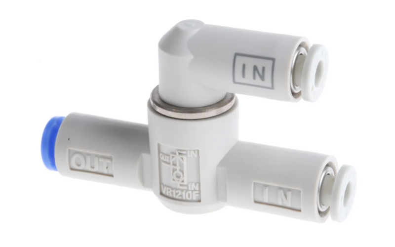
A pneumatic shuttle valve structure includes two inlet ports. Here, the fluid chooses which port to pass through, depending on the pressure. Simply put, if the pressure is too high, the alternate system may control air or liquid flow.
On the other hand, if the pressure is too low, the valve only uses one inlet port. It’s common that if the pressure isn’t too high, the alternate port may never be used.
What is The Function of A Shuttle Valve in A Pneumatic System?
The shuttle valve working principle is by directing fluid flow from more than one source. The primary purpose of the valve is to seal the inlet ports. Note that the valve isolates the regular system from the emergency system.
It is a simple component that plays a huge role in any pneumatic system. A pneumatic shuttle valve operates more than one actuating unit. It may also come with additional outlet ports to allow the switch to the emergency unit when the need arises.
Every inlet port comes with a shuttle seat. If the system operates normally, fluid will flow freely from the inlet port in the regular system. It goes through the valve and into the outlet port.
How Does A Pneumatic Shuttle Valve Work?
If the valve is operating normally, there is a free flow of fluid from the inlet port through the valve. Next, the flow passes through the outlet port and into the actuating unit. It is a simple process and remains in this position unless the alternative system is activated.
When the alternative system is active, the fluid passes from this system to the valve. Finally, it goes through the inlet port. The pneumatic supply from the pneumatic exhaust systems will flow freely to the outlet port.
Note that the fluid will not go through the regular inlet system through the valve. It happens because the valve blocks the normal inlet port when the alternative system is in use. This is the basic mechanism for most valves, including the biased shuttle valve.
Pneumatic Shuttle Valve Types
Ball, spool and poppet are the three pneumatic shuttle valve types found in different pneumatic applications. With different structures and features, their applications may vary depending on the system.
Poppet Shuttle Valve
Often used in engines, poppet pneumatic shuttle valves control the quantity and timing of air passing through the system. If there is a pressure differential on both sides of a poppet valve, it may cause a malfunction.
In exhaust systems, a poppet valve creates a seal if there is higher pressure against it. On the other hand, if there is lower pressure near the inlet port, the valve will open up immediately.
Poppet valves are costly but also efficient. The flow resistance will reduce considerably if there is a huge distance between the upper and lower part of the valve. You can look out for the pneumatic shuttle valve symbol to know whether an appliance has valve inside.
Ball Shuttle Valve
Inside a ball valve, you will find a pivoting ball that controls fluid or airflow. The ball is hollow and perforated to allow proper liquid or airflow. The valve opens when the hole in the ball lines up with the inlet port and closes when out of alignment.
A ball valve is very durable and performs well even after many cycles. As such, it is used in many types of control and shutoff applications. Some types of ball valves include single body, split body, three-piece body, welded, and top entry.
Spool Shuttle Valve
Spool pneumatic shuttle valves control air and oil flow in different systems in both pneumatic and hydraulics. Here, they switch paths where both oil and air can travel. The structure of a spool valve involves a cylinder sealed inside an outer case.
By drilling inside the sealed case, ports are created on both sides. The spool valve works by moving it within the case. As such, it blocks and opens the ports depending on the spool’s location. Moving the spool can be achieved in a few ways. First, you can move it using a lever or a button. Secondly, if the spool valve is part of a large system, you can move it using a solenoid actuator.
Like other valves, spool valves also come in different varieties. Some are available with more than two ports. On the other hand, some spool pressure compensating valves may be used to control multiple equipment simultaneously.
Shuttle Valve Use (Application Parts)
Pneumatic shuttle valve application may vary depending on the industry and the type of equipment.
Clamping and Bending
In clamping and bending applications, these valves are a common component. Here, the valve applies air to the top end of the clamp cylinder, pushing it through a second valve. Next, you will actuate a different valve, allowing it to extend and bend the cylinder.
Finally, you will reset the first valve while the second valve maintains pressure inside the clamp cylinder. When you release the third valve, low-pressure air from reducing a fourth valve will retract the clamp cylinder.
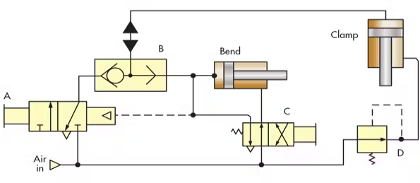
Now, you can vent the pilot line of the first valve and the system begins another operation. Some examples of clamping and bending pneumatic shuttle valve functions include metal sheet fabrication.
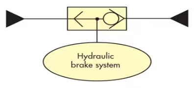
Winch Brake
A winch brake is a hydraulic application where the valve controls braking. After energizing the hydraulic motor in both directions, the valve directs the fluid toward the brake shoes.
After centering the control valve, the brake cylinder immediately vents through the valve. Finally, the brake shoes will close and the process repeats. This pneumatic shut off valve function is applicable during the lifting or lowering of heavy loads.
Alternate Power Inputs
Here, the valve improves control change from one point to the other. Most vehicles come with alternate control stations, each with separate hydraulic inputs. The valve works by directing these inputs to the necessary output.
Hydraulic brake systems use hydraulic shuttle valves for proper function. They are the main braking systems for light trucks and passenger vehicles. Here, the brake fluid transmits force when you apply the hydraulic brakes.
Fluid Motor Crossover
In this system, the valve separates the high-pressure and low-pressure circuit branches. On the other hand, it will direct fluid to the relief valve. Once it reaches here, the valve also replaces back-to-back check valves.
In this application, hydraulic motors will convert fluid pressure into rotary motion. The fluid in the hydraulic pump is pressurized. Next, it converts the motor output shaft by pushing on the hydraulic motor’s pistons, gears and vanes.
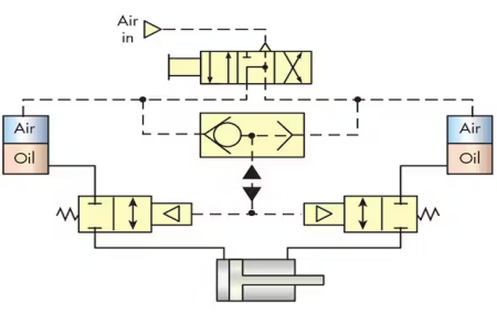
Air Pilot Control
Another function of shuttle valve in pneumatic system is air pilot control. During the air-to-oil conversion, it’s easy for a cylinder to lock in place. The 4-way valve will immediately shift to any of the extreme positions. When this happens, pilot air will go through the valves to keep the air valves open.
It also results in applying oil under air pressure to the other end of the cylinder. When the directional valve is in the neutral position, it results in the exhaustion of pilot pressure. The 2-way valve will close immediately, thereby trapping the oil on both ends of the cylinder.
Standby and Emergency Systems
Pneumatic shuttle valves are also used in controlling the pressure of multiple compressors. They come in handy for compressors that need standby or purge gas capability. These include pressurized cables, instrumentation, or systems that require continuous pneumatic input.
So, how does a pneumatic shuttle valve work in standby emergencies? If the compressor malfunctions, the standby bank, using the valve, immediately takes over. This standby bank is often regulated lower than the compressor supply. The valve immediately closes the inlet port to avoid pressure loss.
When the pressure in the compressor is regularized, the valves closes the standby system. Whether you are switching to an emergency power supply or generator, valves play a key role in this process.
What are The Disadvantages of A Shuttle Valve?
Pneumatic shuttle valves have no mechanical advantages due to the inlet ports on both sides. In the event of lower pressure issues, your system’s high pressure may help regulate this. However, there is a considerable risk of the valve hanging in the middle.
When this happens, both pressures will go to the outlet port. It may lead to a serious fault in your system or application. Understanding the disadvantages of a shuttle valve is important before using it.
In any leakage, the differential pressure is insufficient to move the shuttle. Note that the valve is usually located further away in any system. Therefore, it will take time to move it to allow proper function.
On the other hand, the valve doesn’t have a good seal. As such, it’s tough to create a proper blockage. This will eventually lead to leakage, resulting in malfunction in both the normal and alternate systems.
One outstanding advantage of using pneumatic shuttle valves is the direct connection to the functional parts of your system. However, the disadvantages are costly compared to the advantages. For this reason, you can opt for a manual or mechanical valve.
Conclusion
Pneumatic shuttle valves control air flow from multiple sources in any system. They are available in different types, depending on usage. Ball valves have a ball in the middle that moves to control the flow of liquid or air, depending on the system.
Understanding how these valves work will determine the efficiency of the system. Simply put, if there is a malfunction in the normal system, the valves switch to the alternate system. However, this is coupled with some disadvantages.
For this reason, most people prefer working with mechanical valves over pneumatic shuttle valves. However, there are some outstanding applications for these valves in numerous industrial capacities. They are used in winch brakes, clamping and bending applications, and many more.